VIBRATION / CONDITION MONITORING SYSTEM
INDUSTRY 4.0 APPROACH
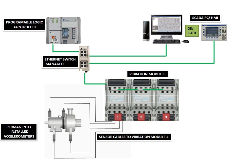
In Vibration monitoring system we use following system architecture:-
- Controller (PLC-compact/control logix) is used to gather data from the Vibration module as per the specified signals provided by the sensors.
- All the data will be stored on the SCADA and reporting PC.
- Monitoring of the large machines can be provided by using the HMI near the Operating area.
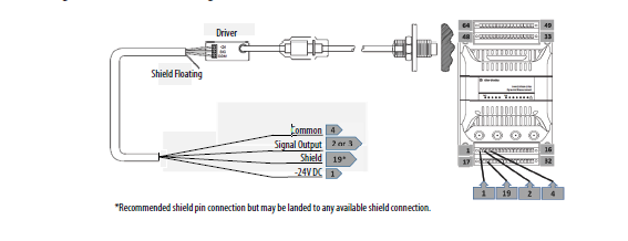
- Basically 3/4 wire sensors can be used for measurement of vibration or condition monitoring.
- Complete system architecture depends on
- ETHERNET PROTOCOL
- ANALOG SIGNALS
EXAMPLES IN INDUSTRIAL USE
Vibration monitoring is very essential for the dynamic as well static machines in the industry point of view. In a running plant over the same platform every machine feels vibration under the tolerable limits. Hence monitoring of such vibration is very much required for long term use of machinery.
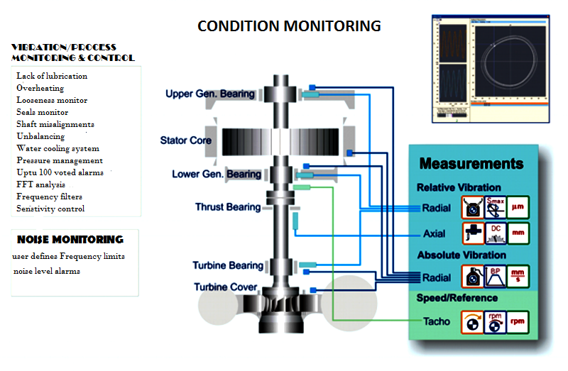
Displacement of shaft with respect to its real axis, rotaional path displacement, x-axis/y-axis displacement of turbine shaft are very critically observant parameters for any rotational machine and we provide all such monitoring and control in our CONDITION MONITORING SECTION.
We provide condition monitoring in following type-
Solution
Developed a highly flexible & cost effective, designed for real time monitoring of overall (direct) vibration levels & we guarantee measurement accuracy within ± 2 microns with Allen Bradley world class Automation control system.
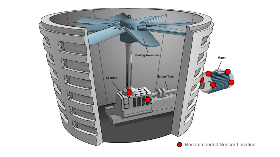
- Hydropower(horizontal/vertical) turbine
- Thermal power turbine
- Extruder machinery
- FMCG industries
- Blower in heavy industries
- Power motors
- Diesel Generators turbines
Generally 1444 dynamix series works on Ethernet protocol for which there are 2 RJ45 port for connection.
1444 dynamix module can be easily configured in RS logix 5000 software and hence can be communicate very easily with COMPACT as well as CONTROL logix series.
For real time monitoring purpose all the sensor values can be monitored over generally use SCADA systems.And hence calibration of the sensors can easily be done by changing the limits directly from control room once after a sensor is installed in the field.
Separate relay module can be used for controlling the field output as per the vibration limits set by the user for Individual machines.
Extension channels for more than 4 sensors can be added to the very left hand side of the previous 1444 module by using very minimum wiring.
SCADA/HMI representation
- The VMS details will be displayed over the SCADA Screen as per machine for each installed sensor.
- Vibration can be measured in the following terms
- ACCELERATION (micro/sec2, mm/sec2, met/sec2, mil/sec2)
- VELOCITY (micro/sec, mm/sec, met/sec, mil/sec)
- DISPLACEMENT (micro, mm, met, mil)
- Signals can be easily configured with the controller as per industry standard output
- 0-10 voltage
- 4-20 Ma
- Easily configurable alarms for threshold and tripping alert.
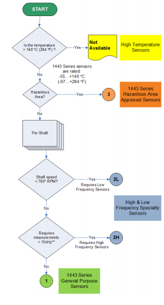
- Sensors can be mounted as per machine requirement
Non-contact type sensors- this sensor works when flux lines cut by a specific quantity of torque and hence no of lines cut can easily be converted into electrical quantity.
- Eddy current probes are basically used for non contact type sensors.
- This probe works for the change in set GAP VOLTAGE for the required rotating part. And a required torque is needed to change the voltage gap and change in such analog signal is converted into DISPLACEMENT by a Voltage transducer.
- On the basis of such theory we can monitor the shaft position with respect to its ZERO position in terms of MICRON/INCH/MM/METER/MIL.
- Sensors can be mounted as per machine requirement
- Contact type
- Non-contact type
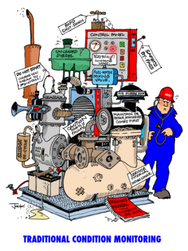
WHY AND WHEN VMS REQUIRED
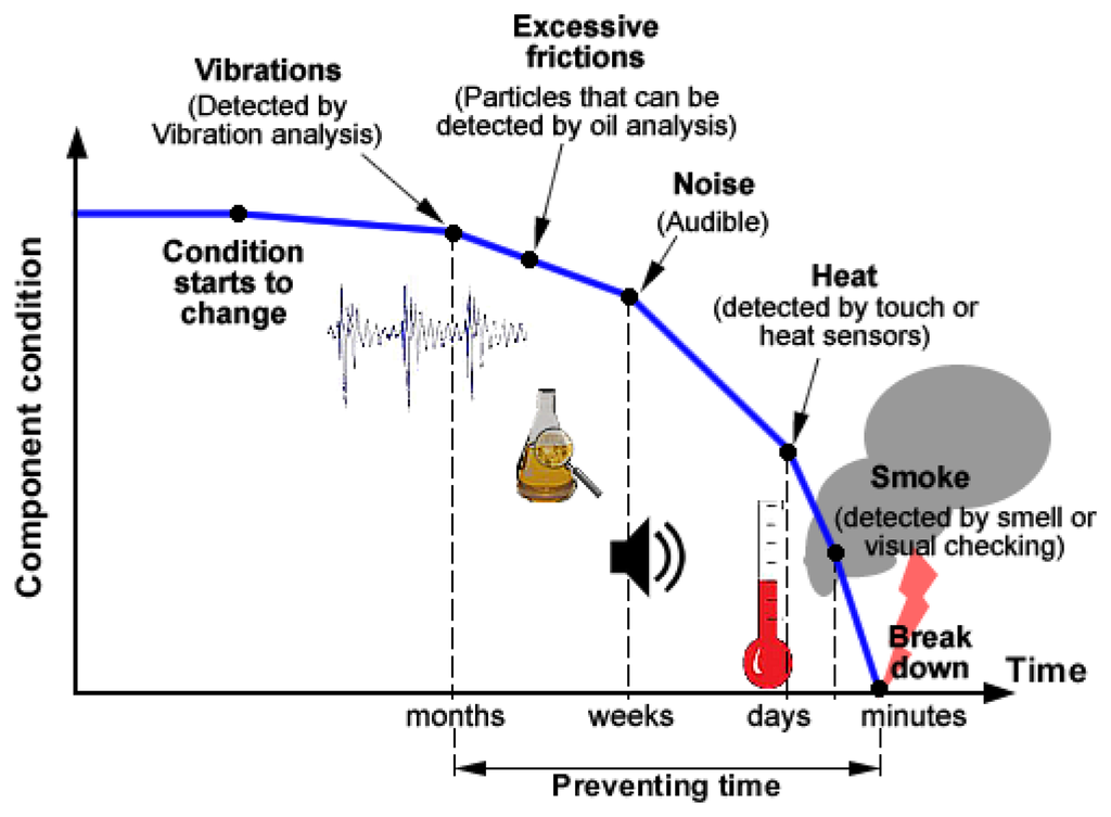
Condition monitoring is very much required these days.
As per study in the industry all face the problems during machine operation due to vibration presents in the machine. A typical analysis can be present as-
HOW IT CAN BE ANALYSE FOR CONFIGURATION
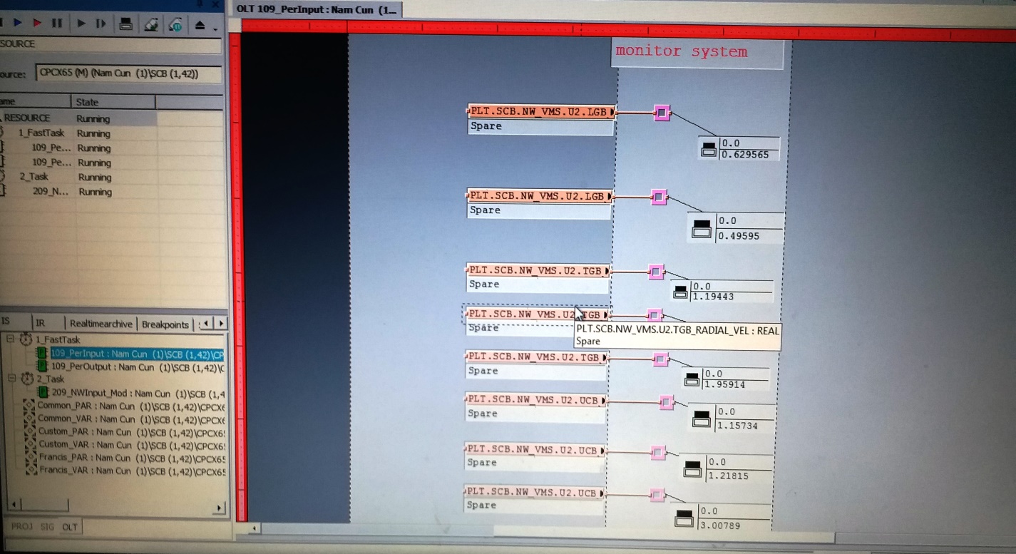
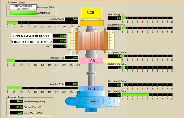
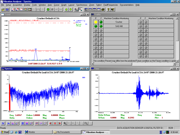
The final analysis can be done by comparing every sensor report with respect to REAL TIME MONITORING.
A typical REAL TIME REPORT is shown below
Third party communication
We provide communication by well known IEC 104 protocol, our controller (compact/control logix series only) can be easily configured either as a slave or as a master for other third party controllers.
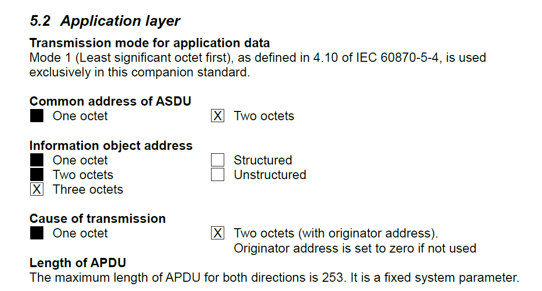
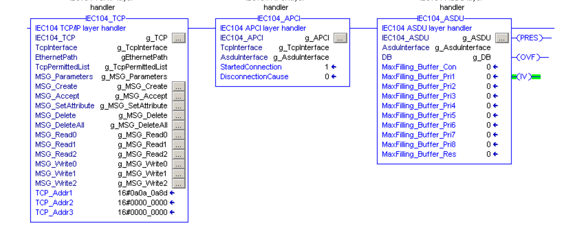
Following is the example of ALLEN BRADLEY and SIEMENS make controllers communication over IEC 104 protocol and in such mode we can configure our controller only for monitoring purpose even in the SLAVE mode.