Being a Automation Solution provider to Many Automotive manufacturing units and their vendors also, we take pride in providing the solutions such as furnance control, Paint shop automation, conveyor line automation, Andon (OEE for machine, line and plant) System. To name few ASAHI, Escorts, JCB, Bajaj Motors, Hero Motors, Hardley & Davidson. Etc.
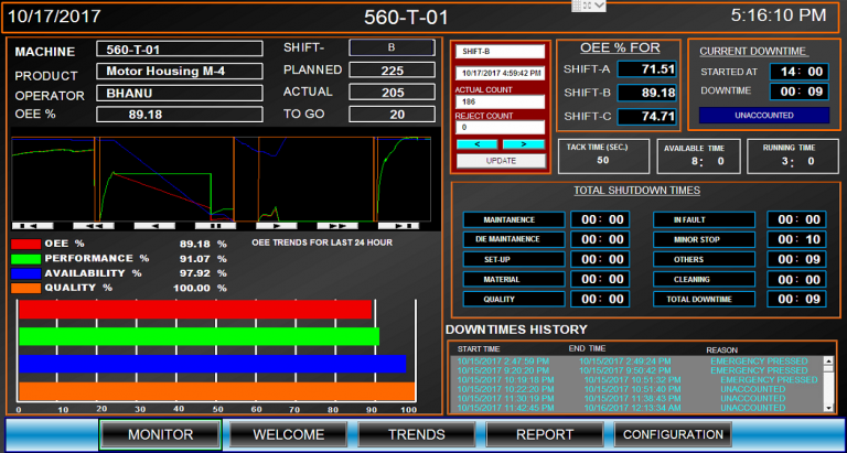
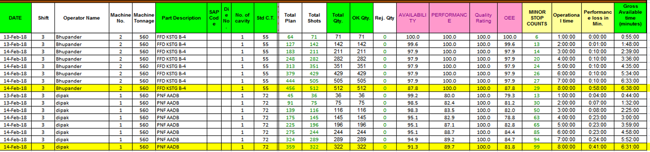
OEE breaks the performance of a manufacturing unit into three separate but measurable components: Availability, Performance, and Quality. Each component points to an aspect of the process that can be targeted for improvement. OEE may be applied to any individual Work Center, or rolled up to Department or Plant levels. This tool also allows for drilling down for very specific analysis, such as a particular Part Number, Shift, or any of several other parameters. It is unlikely that any manufacturing process can run at 100% OEE. Many manufacturers benchmark their industry to set a challenging target; 85% is not uncommon.
- OEE is calculated with the formula (Availability)*(Performance)*(Quality)
- Using the examples given below:
- (Availability= 86.6%)*(Performance=93%)*(Quality=91.3%)= (OEE=73.6%)
Alternatively, and often easier, OEE is calculated by dividing the minimum time needed to produce the parts under optimal conditions by the actual time needed to produce the parts. For example:
- Total Time: 8 hour shift or 28,800 seconds, producing 14,400 parts, or one part every 2 seconds.
- Fastest possible cycle time is 1.5 seconds, hence only 21,600 seconds would have been needed to produce the 14,400 parts. The remaining 7,200 seconds or 2 hours were lost.
- The OEE is now the 21,600 seconds divided by 28,800 seconds (same as maximal 1.5 seconds per part divided by 2 actual seconds per part), or 75%.
OEE is the ratio of Fully Productive Time to Planned Production Time. Schedule Loss is not included in OEE calculations since there is no intention of running production.
An example of OEE application developed for one of our Major Automotive Customer is given below. An example of OEE application developed for one of our Major Automotive Customer is given below.
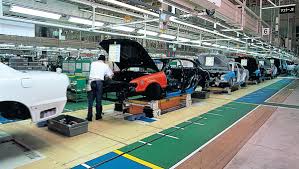
Conveyor line automation using PLC and AC DRIVES CONTROL. Synchronisation of main assembly line with sub-assembly lines in master-slave format .
Varying line speed using AC drives and using shearing pin feature protecting conveyor line breakdown , is one of the several features incorporated using automation.
We do undertake conveyor line automation for material handling , assembly, paint-shop, etc.
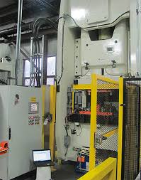
Safety has become very essential and mandatory in all the industries from Operator Prospective and Machine Performance as well. Various safety applications can be developed to avoid accidents on the shop Floor using safety drives, safety PLC, Safety Motion and Motor control , presence sensing safety devices( Hand detection safety sensor, safety mats, safety edge profiles , safety light curtains and safety laser scanners), Safety relays and safety switches.
Now a days we find special mention of Robotic Cell Safety because of life loss due to Mal functioning of the Robots and various manufacturing locations
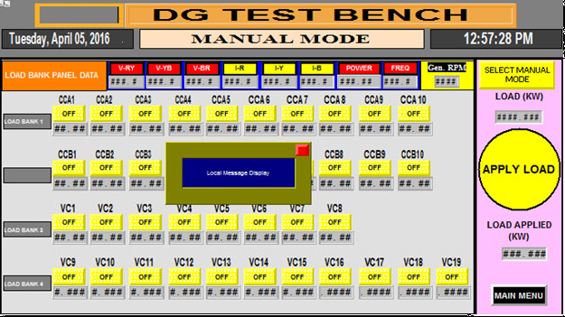
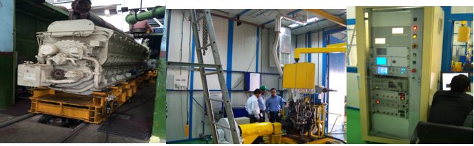
Load Bank – It is a device which develops an electrical load, applies the load to an electrical power source and converts or dissipates the resultant power output of the source. The purpose of a load bank is to accurately mimic the operational or “real”load that a power source will see in actual application.
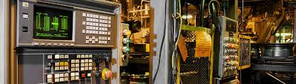
Operation and Monitoring – D.G testing is controlled and monitored by SCADA (Factory Talk View SE) and data process control and calculations are done by PAC (Compact logix) & PLC (Micrologix).
Process Description – D.G connected to load bank by checking correct connections of phases.
Then by SCADA data and values are updated according to model number, and load test is started by SCADA.
When the test is running Micrologix 1400 plc reads data from DEEP SEA CONTROLLER which is connected to D.G . Data transfer of DG is done by MODBUS communication.
Then the micrologix 1400 data is messaged to compact logix , which do all the calculation and process accordingly.
After the completion of load test report is generated for all steps as required by operator.
Report include following basic data:-
- KW Load
- AC Voltage
- HERTZ Frequency
- Oil Pressure
- Ampere Rating
- Voltage tested
- Additional by requirement
To implement a machine vision application successfully, a developer needs to know precisely what it needs to achieve. That makes it essential to understand the characteristics of the parts and subassemblies which the vision system will examine, as well as the specifications of the production line itself. The key characteristics include: ·
- Specific part dimensions
- Part tolerances
- Needed level of measurement precision
- Minimum size of defects to be detected
- Speed of the production line
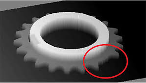
With a comparatively modest investment in machine vision, a major European automobile maker has solved a critical quality challenge in its gear assembly bearings. Before installing the vision system on the production line, the company found it nearly impossible to ensure 100% accuracy—an especially thorny problem because of the safety implications. The machine vision system has now remedied the situation by automatically verifying the presence of all bearings in each assembly and gaging their diameters to make certain they are correctly shaped and undamaged. The company is also taking advantage of the vision system’s “point & click” simplicity with a customized interface that makes it easy for operators to use the system correctly with a minimum of training. Other companies around the world are similarly using machine vision for engine and power train applications such as:·
- Gaging nozzle holes on oil jet pumps
- Inspecting adhesives applied to gear boxes
- Verifying the presence and correct shape of gear teeth
- Reading characters on engine blocks with OCR functions
- Detecting defective seals on engine blocks
- Inspecting engine castings for defects
- Checking and identifying engine block types before assembly
- Gaging the gaps on spark plugs
- Verifying the presence of critical stoppers on fuel injection pumps
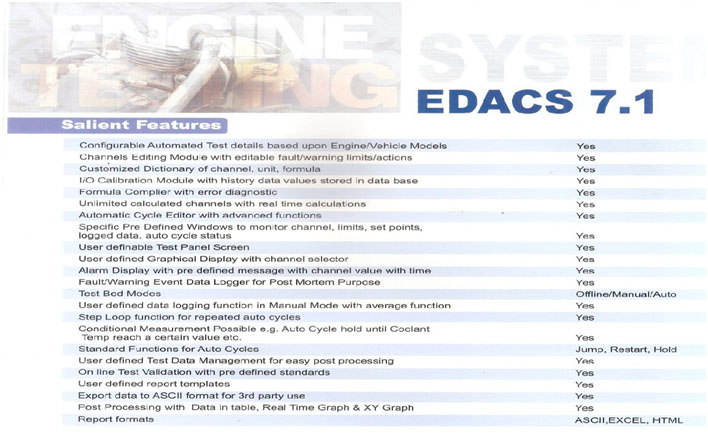
EDACS is a Labview based fully automated Engine Data Acquisition & Control System which can be used for Production; quality as well as R&D applications. The core strength of this system is its open architecture, which helps it to be interfaced with almost any Dyno Controller and almost any Data Acquisition System with Real Time Capabilities. It performs integrated operations with multiple devices like Throttle Controller, smoke meter, fuel meter, blow by meter, emission annalyser, etc.